Allion Labs / Paul Chou
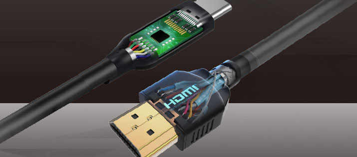
With the rapid development of technology, there is a growing demand for high-speed audio and video data transmission. The connectors and cables used by our daily public are gradually upgrading. For example, the specification of HDMI has evolved from HDMI 2.0 to HDMI 2.1, and the transmission rate is enhanced from 6.0 Gbps to 12 Gbps. Moreover, the speed of USB 3.2® Gen 2 also reached 10 Gbps, and it is expected that USB4® will reach 20 Gbps as well, which is the same as Thunderbolt3.
 While users are enjoying excellent transmission quality and immediacy, the quality of the connectors and cables will directly affect the user experience. For example, when a user plugs an uncertified cable into a device, the device might not respond.

Five Types of Potential Risks in High-frequency Testing
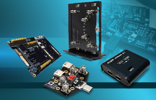
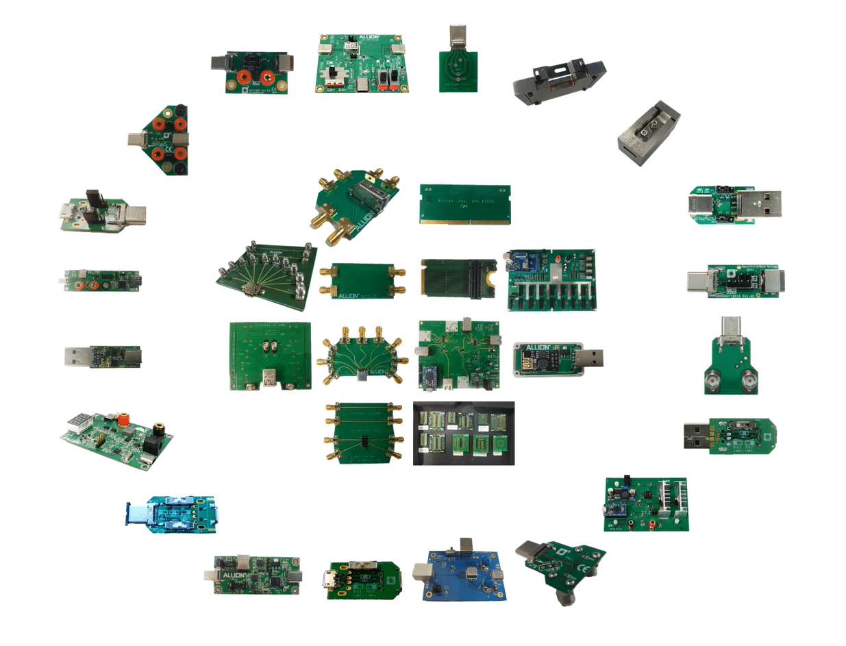
As a connector association certification laboratory, Allion Labs can conduct a Verification Test for customers and provide the relevant high-frequency fixture design for testing. Since 2016, Allion Labs have been provided custom-designed high-frequency measuring fixture design services for standard or special-sized connectors. Over the years, Allion Labs have accumulated experiences in designing high-frequency fixtures for hundreds of cases. Because of this, Allion Labs would like to share the following five types of potential risks that occur most frequently during high-frequency testing:
Impedance matching refers to the most efficient transmission of signal power from the source to the load, so that the signal does not reflect as much as possible during transmission.
Issue: If the impedance mismatch occurs, it will cause reflection. Therefore, energy transfer will not pass through and efficiency will be reduced, which will lead to adverse effects, such as oscillation and radiation interference.
The coupling interference between the two signal traces can be divided into near-end and far-end interference.
Issue: When crosstalk interference occurs, it will affect signal integrity.
Attenuation refers to the reduction in the signal transmission and it occurs in the high-frequency signal transmitted from A to B.
Issue: When the attenuation in the frequency domain occurs, it will cause adverse effects, such as poor signal transmission and low efficiency.
Return loss is the phenomenon that the high-frequency signal is reflected by the input signal due to impedance mismatch.
Issue: When the return loss occurs, it will cause energy to be reflected and the efficiency to be reduced.
The difference between far-end crosstalk and attenuation.
Issue: When ACR occurs, it means that Crosstalk and Insertion Loss may also have corresponding problems, which may result in signal integrity and signal efficiency degradation.
| Potential Risk | Improve Method |
| Impedance NOT matching
|
• Adjust PCB impedance characteristics to reduce the effects of high-frequency fixture boards on cables and connectors, which needed to be tested.
• To optimize customer provided pin design specifications and to reduce signal attenuation. |
| Attenuation
(Insertion Loss) |
• Provisioning on circuit design.
• Selection of high-frequency PCB materials. • Processing method (tin will affect). |
| Crosstalk
ACR (Attenuation to Crosstalk Ration) |
• Be conscious of the traces are too close, you can use the via to reflow the signal.
• To reduce interference, the trace should not have green paint. • Differential pair can be placed in one-to-one mode to reduce interference. |
Corresponding Solutions to Five Major Problems
Practical Cases in High-Frequency Fixtures
We offer customized high-frequency fixture solution based on test verification and practical cases, which helps to maintain the good quality of your product. Here are the practical cases we have collected from high-frequency fixture design.
Example 1: An impedance mismatch is caused by the contact surface on the fixture board, which does not match at the junction of the pin and the fixture.
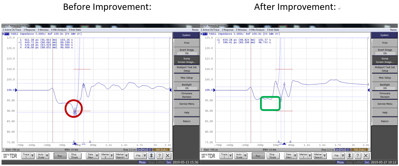
Solution: In order to avoid excessive capacitance effect resulting in lower impedance, we suggest to reduce the connection area between the pin and the fixture board.
Example 2: Impact of Insertion Loss caused by client connector processing.
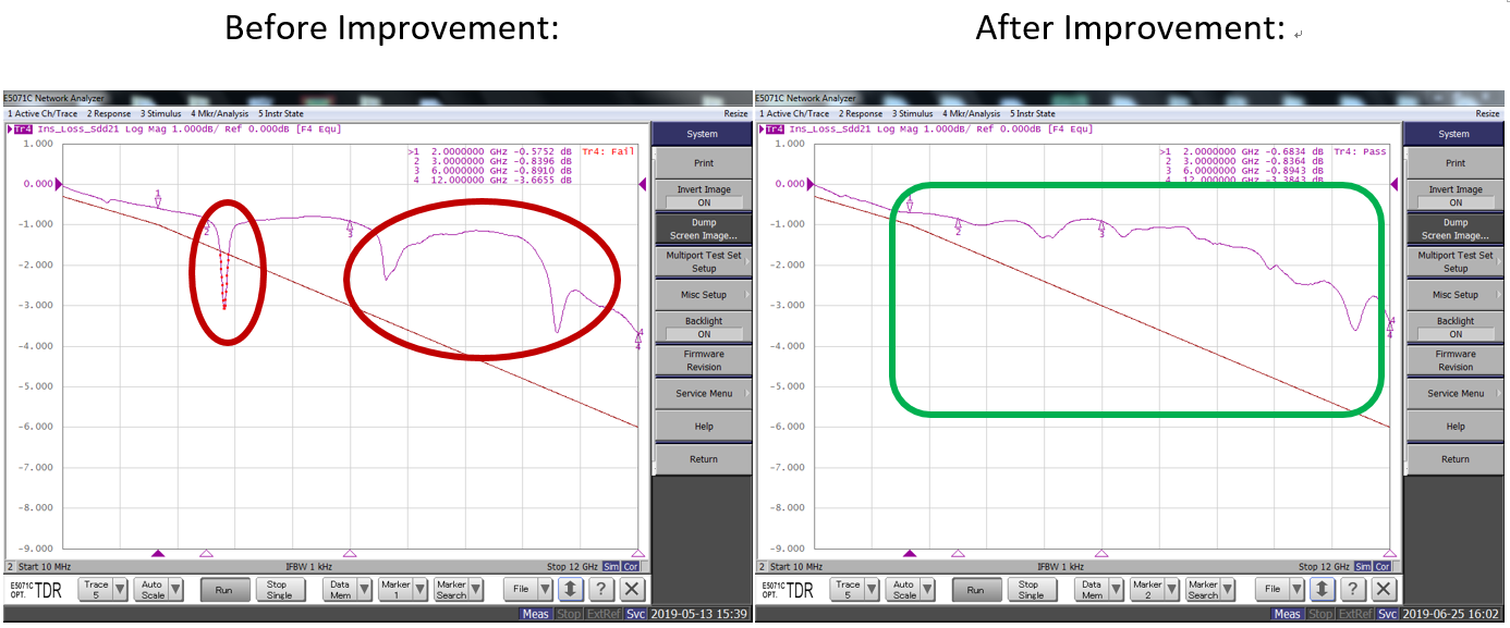
Solution: Improve processing of tinning and reduce Insertion Loss.
Example 3: Traces on the same plane that are too close to each other cause Crosstalk.
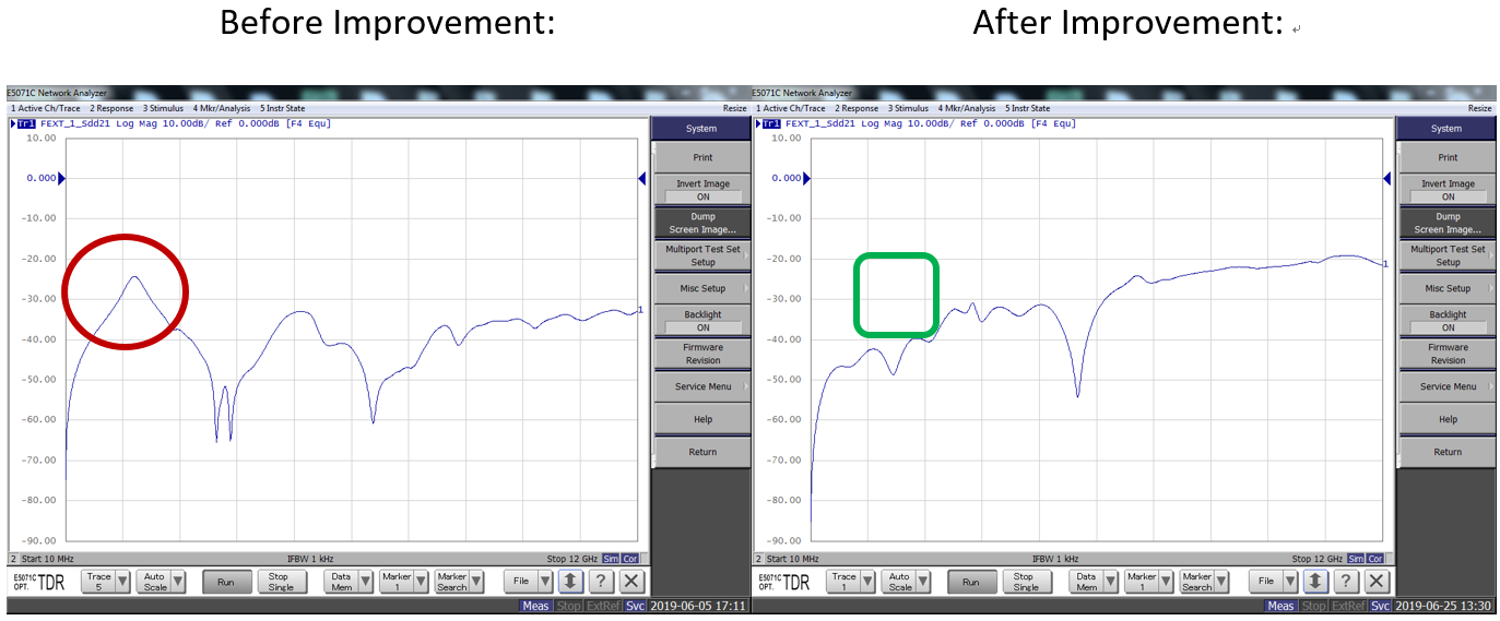
Solution: To reduce the crosstalk results from nearby signals, adjacent Differential pairs should use different levels of routing. At the same time, using the path (via) is to shorten the return path of the signal.
Example 4: HDMI ACR Test Failed.
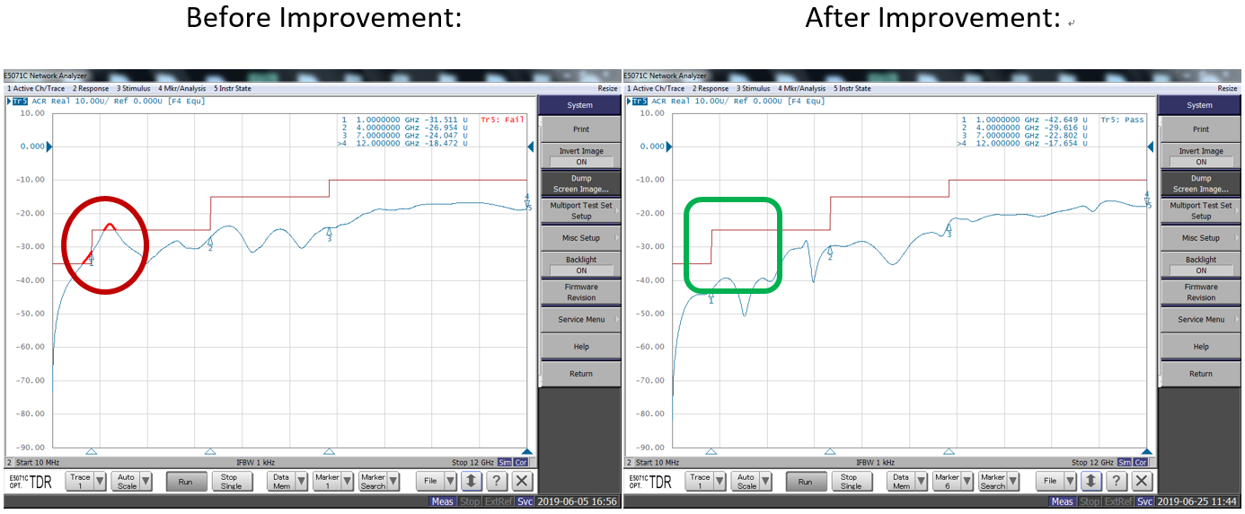
Solution: Since ACR is a test for the difference between far-end crosstalk and attenuation, via reducing Crosstalk & Insertion Loss, it is easier to pass the ACR test.
Cable and Connector Fixture Services and Test Services at Allion
The design of high-frequency fixtures has become a vital part of cables and connectors validation. At present, only Allion can provide customers with a comprehensive one-stop verification testing, from product design, test fixture and even to get a final certification. We can help our consumers get relevant certifications in the shortest time possible. If you have any requirements, please contact the Allion Test Service Department or refer to the following website for further information: https://allion.com/test-lab/cabconlab/
Technical Highlights

